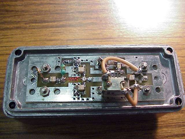
Bi-Directional 2.4 GHz One Watt Amplifier With Receive Pre-Amp Bi-Directional 2.4 GHz One Watt Amplifier With Receive Pre-Amp Some designs are for research only. Advanced microwave and RF design skillz will be required to build these circuits. This will show you how to add a bi-directional, 2.4 GHz amplifier to your Proxim Symphony for under $100. Bi-directional means you can mount the amplifier at the antenna to help overcome any cable loss, and the amplifier will automatically switch between receive and transmit modes. The cost is reduced by using readily available materials and components.
The DSC-R414 Wideband RF Amplifier from 30 kHz to 45 GHz frequency band, is a general purpose, small footprint, RF amplifier, with moderate gain. The amplifier is useful for applications such as optical communications and 25G/40G VCSEL drivers.
Also, instead of a complicated RF sensing transmit/receive switch, a logic level indication of transmit is sent to the amplifier through a length of low cost coaxial cable. The final RF power output of this amplifier will be around +31 dBm (1.3 watts) and the receive gain is around 16 dB (with a 2 dB noise figure). If adapting for use on direct sequence spread spectrum systems, you'll want to lower the overall P1dB (+28 dBm or so) to keep the RF power amplifier in its linear region. To do this, attenuate the RF input power slightly. Receive amplification is tricky subject. When done right, it works wonders. When done wrong, your stuck listening to shortwave broadcast stations in Yugoslavia.
If you don't need to have the receiver amplifier (due to excess local noise/intermodulation or loss coax loss), just replace it with a stripline jumper. If you're too stupid to figure that out, then please don't build these. Adaptation to wireless network cards other than the Proxim Symphony should be trivial. Schematics Most schematics are in their native PostScript format for ease of printing and modification. To use PostScript under Window$, you'll need to install the. Set Media to A2 for ease of viewing. • Block diagram • First original design - reference only - don't build • Second original design - reference only - don't build • Includes an experimental idea for remote RF sense.
Newest design - reference only - work in progress • Untested - reference only • Untested - reference only Commercial Amplifiers Here are some really nice commercial 2.4 GHz amplifiers. • Nice idea with amp built into the antenna. • • Sells multi-band amplifiers & converters. FCC Records & Pictures of Commercial Amplifiers • • • (20k PDF) • (34k PDF) • Includes parts list! • • • • • • • • • • • • • • Construction Notes Start by reading the for the RF2126 1 watt 8-pin PSOP 2.4 GHz amplifier IC. If you are up to working with this device, call RFMD up at 336-664-1233 and order a few (around $7 each), or ask if they will send you some free engineering samples.

Next, read the for the HFA3424 2.4 GHz - 2.5 GHz low noise amplifier. It's also a 8-pin PSOP device. You can order these for around $8 each from. Next, read the for the RF1K49093 8-pin PSOP power MOSFET.
You can order these for around $2 each from. You'll want to pick up some quality 1/32 inch, double-sided, one ounce oz copper clad FR-4 circuit board. Choot mein sajane wala sexy video pc high quality.
The circuit board from is perfect. Its part number is PC44-ND for 3 x 4.5 inches and costs $3.23. Teflon circuit board has better characteristics at microwave frequencies so use that instead if you can find it. And sell Teflon board. Note that you will need to change the widths of all the 50 ohm striplines in the schematic due to the lower dielectric constant of Teflon board material.
The standard MinnowBoard development board firmware is demonstrated; however, the method illustrated in this tutorial can also be used to load any of the alternative boot loader firmware options available for the MinnowBoard development boards. You can use the tool to flash firmware on multiple boards in quick succession, and this method is especially handy for this serial bulk programming use. Spi flash winbond.
Now, make the circuit board for the amplifier. You'll have to do this by hand until someone makes me a PCB pattern. You can use those rub on thingys from Radio Shack ( #276-1490) to layout the pattern. The 1 mm wide traces are almost perfect for 50 ohm striplines on 4.34 er, 1/32 inch FR-4 board material (actual width required is 1.4 mm) and the 2 mm traces are perfect 50 ohm for striplines on 2.55 er, 1/32' Teflon board material.